
Several terms used throughout the VMX-pi libraries and documentation may not be commonly understood and are defined herein.
Basic Terminology
A working knowledge of the following Basic Terminology is highly recommended when working with VMX-pi or any other Inertial Measurement Unit (IMU).
Pitch, Roll and Yaw
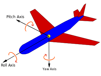
Pitch, Roll and Yaw are measures of angular rotation about an object’s center of mass, and together provide a measure of “orientation” of that object with respect to an “at rest” position. When units of degrees are used, their range is from -180 to 180 degrees, where 0 degrees represents the “at rest” position of each axis.
| Axis | Orientation relative to object’s center of mass | Rotational Motion |
| X (Pitch) | Left/Right | + Tilt Backwards |
| Y (Roll) | Forward/Backward | + Roll Left |
| Z (Yaw) | Up/Down | + Clockwise/ – Counter-wise |
Important Note: Pitch, Roll and Yaw angles represent rotation from the “origin” (0,0,0) of a 3-axis coordinate system. VMX-pi Pitch and Roll angles are referenced to earth’s gravity – so when VMX-pi is flat, Pitch and Roll angles should be 0.
The Yaw angle is different – Yaw is not referenced to anything external. When VMX-pi startup calibration completes, the Yaw angle is automatically set to 0 – thus at this point, 0 degrees represents where the “head” of the VMX-pi circuit board is pointing. The Yaw angle can be reset at any time after calibration completes if a new reference direction is desired.
Linear Acceleration
Linear Acceleration is a measure of the change in velocity in a specific direction. For example, when a car starts from a standstill (zero relative velocity) and travels in a straight line at increasing speeds, it is accelerating in the direction of travel.
| Axis | Orientation | Linear motion |
| X | Left/Right | – Left / + Right |
| Y | Forward/Backward | + Forward / – Backward |
| Z | Up/Down | + Up / – Down |
Because the gyroscope and accelerometer axes are aligned, VMX-pi measures linear acceleration in the same set of 3 axes used to measure Pitch, Roll and Yaw. However unlike Pitch, Roll and Yaw, acceleration measures linear motion rather than rotation, and is measured in units of G, with a range of +/- 2.0.
Compass Heading
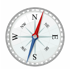
A compass measures the earth’s magnetic field and indicates the current direction (heading) relative to magnetic north (N). Compass Heading is measured in degrees and is similar to Yaw, but has a few key differences:
- Compass Heading has a range of 0-360 (where magnetic north is 0).
- Compass Heading is absolute – it is referenced to magnetic north, and thus Compass Heading does not drift over time
Important Note 1: Compass Heading relies upon being able to measure the earth’s magnetic field. Since the earth’s magnetic field is weak, Compass Heading may not be able to measure earth’s magnetic field when the compass is near a strong magnetic field such as that generated by a motor.
Important Note 2: Magnetic North is not exactly the same as True North. Your robot can calculate True North given a Magnetic North reading, as long as the current declination is known. Declination is a measure of the difference in angle between Magnetic North and True North, and changes depending upon your location on earth, and also changes over time at that same location. An online calculator is provided allowing one to calculate declination for a given earth location and date.
Altitude
Altitude is a measure of distance in the “up” direction from a reference; VMX-pi (Aero Edition) calculates altitude above sea-level using a pressure sensor.
VMX-pi (Aero Edition) altitude has a range of 0 to 25,000 meters.
Important Note: Altitude is calculated based upon barometric pressure. In order to accurately estimate altitude above the earth, VMX-pi should be configured with the sea-level barometric pressure in the surrounding area. This setting can be configured via the VMX-pi Advanced Configuration Tool.
3-D Coordinate System

VMX-pi 3-D Coordinate System
A 3-D Coordinate System uses one or more numbers (coordinates), often used to uniquely determine the position of a point within a space measured by that system. The origin of a 3-D coordinate system has a value of (0, 0, 0).
VMX-pi features gyroscopes, accelerometers and magnetometers which are all aligned with each other in a 3-D coordinate system. Each sensor type measures values with respect to that coordinate system, as follows:
Gyroscopes: measure rotation (as shown in the green arrows) about each axis. The coordinate system origin represents the center of the VMX-pi circuit board.
Accelerometers: measure acceleration, where the origin represents the position in space at which the previous acceleration sample was acquired.
Magnetometers: measure earth’s magnetic field, where the origin represents the center of the VMX-pi circuit board.
Important Note: Because the VMX-pi Gyroscopes, Accelerometers and Magnetometers are all aligned to this 3-D Coordinate System, VMX-pi’s motion processor can also use Sensor Fusion to provide additional information and processing including Tilt Correction, “Fused Heading”, a Gravity Vector, World Reference Frame-based Linear Acceleration and Quaternions, as discussed in the Motion Processing section below.
Motion Processing
Users should also have a working knowledge of the terms defined in the Motion Processing Terminology.
Tilt Correction
Without correction, the compass heading calculated by a 3-axis magnetometer will only be accurate if the magnetometers are held “flat” with respect to the earth. To ensure the compass heading is valid even in cases when the sensor is “pitched” (Pitch angle != 0) or “rolled” (Roll angle != 0), VMX-pi performs “tilt correction” fusing the reading from the magnetometers with the pitch and roll angles from the accelerometers. Once corrected, the compass heading is aligned with the VMX-pi Z axis, which ensures that the Yaw angle and the Compass Heading measure rotation similarly.
“Fused” Heading
Given the gravity-referenced orientation provided by the Yaw angle, as well as the absolute compass heading angle which has been aligned to the VMX-pi 3-D coordinate system, both angles can be fused together. As shown in the table below, over a period of several minutes this can minimize the drift inherent in the Yaw angle, as well as provide an absolute reference for the Yaw angle – as long as the magnetometer is calibrated and a valid magnetometer reading is available every minute or so.
| Value | Accuracy | Update Rate | Drift |
| Yaw | .01 degrees | Up to 66 Hz | ~1 degree/minute |
| Compass Heading | 2 degrees | 1 Hz (if not magnetically disturbed) | None |
| Fused Heading | 2 degrees (as long as a valid magnetometer reading is received in the last minute or so) | Up to 66Hz | None (~1 degree/minute, during periods of magnetic disturbance) |
Like the Compass Heading, the Fused Heading has a range from 0-360 degrees.
Important Note: If the Compass Heading is not valid, the Fused Heading origin is the same as the Yaw angle. When valid (magnetically undisturbed) compass readings are received, the Fused Heading’s origin shifts to magnetic north (0 degrees on the Compass).
Gravity Vector
Accelerometers measure both acceleration due to gravity, as well as acceleration due to linear acceleration. This fact makes using raw accelerometer data difficult. VMX-pi’s automatic accelerometer calibration determines the component of measured acceleration which corresponds to gravity, and uses this information together with gyroscope readings to calculate a gravity vector, which represents acceleration due to gravity. Pitch and Roll angles are derived from this gravity vector.
Once the gravity vector is understood, this value is then subtracted from the raw accelerometer data to yield the acceleration due to linear motion.
Velocity and Displacement
Acceleration is defined as the change in Velocity. Therefore, linear velocity can be calculated by integrating linear acceleration over time.
Velocity is defined as the change in Position, otherwise known as Displacement. Therefore, linear displacement can be calculated by integrating linear velocity over time.
Important Note: Using currently-available MEMS-based accelerometers to calculate linear velocity and displacement is subject to large amounts of error primarily due to accelerometer “noise” (a difference between the actual acceleration and the measured acceleration inherent with MEMS sensors). This noise not only accumulates, but is also squared in the case of velocity, and is cubed in the case of displacement. Therefore, the resulting estimated velocity and displacement values are not typically useful for robotic navigation. The amount of error in displacement estimation can be several feet per second. As MEMS sensors improve in the coming years and accelerometer noise is reduced by approximately 100 times its currently value, this technique will become more useful for robotics navigation.
If you would like to experiment with using the VMX-pi to calculate displacement and velocity, you can use the navXUI’s “Experimental” button to bring up a dialog which displays the integrated velocity and displacement values calculated in real-time by the VMX-pi.
World Reference Frame
Raw acceleration data measures acceleration along the corresponding sensor axis. This measurement occurs in a reference frame known as “Body Reference Frame”. This works well as long as the VMX-pi circuit board is in it’s original orientation. However as the VMX-pi circuit board rotates, the X and Y accelerometer axes no longer point “forward/back” and “left/right” with respect to the original orientation. To understand this more clearly, consider how the meaning of the term “left” changes once a robot has rotated 180 degrees? Introducing a World Reference Frame solves this issue by providing a reference upon which to measure “leftness”.
To account for this, VMX-pi’s motion processing adjusts each linear acceleration value by rotating it in the opposition direction of the current yaw angle. The result is an acceleration value that represents acceleration with respect to the area in which VMX-pi operates, which is known as “World Reference Frame”. This world-frame linear acceleration value is much simpler to use for tracking motion of an object, like a robot, which might rotate while it moves.
Important Note: VMX-pi Linear Acceleration values are in World Reference Frame.
Advanced
Advanced users may require knowledge of the following terminology.
Quaternions
A quaternion is a four-element vector that can be used to encode any rotation in a 3D coordinate system. This single 4-element vector value can describe not only rotation about a reference frame’s origin (Pitch, Roll and Yaw) but also the rotation of that entire reference frame with respect to another. Furthermore, when Pitch, Roll and Yaw measures to perform certain calculations, it is not possible to clearly ascertain orientation when two axes are aligned with each other; this condition is referred to as “Gimbal Lock”. For robotics applications, Pitch, Roll and Yaw are sufficient, however for certain aerospace applications, Quaternions may be required to handle all possible orientations.
VMX-pi uses Quaternions internally, and also provides the 4 quaternion values for use by those who might need them.